Diptronics Manufacturing Inc. is a manufacturer specializing in DIP, Tact, Rotary, Slide, Detector, Multi-functional, Micro and Illuminated switch manufacturing. (Source) The T3C tact switch is one of the products with the highest output in Diptronics Manufacturing Inc. The main purpose of electronic switches is to turn on the circuit. This kind of product is easy to have air trap, weld line and lack of material in the manufacturing process, resulting in poor conduction of the product. The team used Moldex3D to find out the solutions to balance the flow behavior of products, shorten the molding cycle, and improve appearance defects. Applying Moldex3D can effectively improve the product yield and reduce costs at the same time. The team used Moldex3D to analyze and change the position of the runner to balance the flow behavior of the filling product and reduce the residual stress. Then, by changing the part design and mold design, they improved the air trap, weld line and lack of material issue. The application of Moldex3D has increased the yield to 39.68%, and the production cycle was also shortened by 16%. In this study, the product is a T3C tact switch, with size 3mm * 2mm * 0.6mm. The mold is designed as an eight-cavity mold (Fig. 1), The average thickness of the inner cavity is 0.06 to 0.09mm, which made the processing technique more difficult than general manufacturing. According to the Moldex3D simulation, there was indeed a phenomenon of flow imbalance where the inner fills faster than the outer part due to the fish-bone runner design (Fig. 2). The max cooling time was also too long at the runner region which led to a longer molding cycle time by around 7 to 8 seconds (Fig. 3). Further observation showed that the weld line (the red line segment in Fig. 4) was concentrated at the recessed hole at the back of the product, along with  the flux being easy to leak, resulted in poor product conduction. In addition, the max shear stress (Fig. 5) was around 6 MPa, which is too high, causing the plastic to crack and excessive residual stress. According to the simulation results and experimental verification, it is clearly shown that the runner design is the key to affect the flow balance. Through the analysis of Moldex3D and several actual verifications, the new runner design was chosen to replace the original solution. Diptronics decided to apply S-shape runner to achieve flow balance (shown in Fig.6). Runner balancing in multi-cavity molds improves the chance that all cavities will fill and pack at the same time. Runner balancing is highly recommended for multi-cavity molds and bringing more cavities into the mold can benefit productivity. In this step, the redesign of the runner system was evaluated in Moldex3D, and several issues were solved such as flow imbalance (Fig. 7), high shear stress and long cycle time. The shear stress is reduced from 7MPa to 3MPa in the new S-shape runner layout (Fig. 8 a) while the max cooling time is reduced from 8sec to 5sec (Fig. 8b). Moreover, the S-shape runner system also saves 11% of materials reducing the costs of manufacturing (Fig.9). However, it could not help to solve the weld line and air trap issues by only changing the runner system; Furthermore, it would be necessary to remove the concave hole which was 0.03 to 0.05mm deep (Fig. 10a) and replace the ejector pin to four external ones (Fig. 10b) to eliminate weld line and air trap. As the results of the manufactured part showed (Fig. 11), the weld line has moved to the top shown in the red line cycle in the figure, which is better than the original design. The actual verification also matches the simulation results. See in detail, the original design with a concave hole shows an apparent weld line, as shown in the red line cycle in Fig. 12. After removing the concave hole and replacing the ejector pins, the final optimal design meets the requirements of manufacturing. Moldex3D can help achieve tooling with much lower cost and provide early diagnosis of molding defects, such as flow imbalance, weld line and air trap, and further help save significant amounts of production money and mitigate risks before the production. Full Thread,Full Thread Small Cap Rolling Nail,Yellow Paint Small Cap Roofing Nail,Small Cap Roofing Nail Hebei Xinduan Hardware Manufacturing Co. , Ltd. , https://www.xinduanhardware.com
Edited by Jasmine Ho, Engineer at Technical Support Team, Moldex3D
Summary
Challenges
Solutions
Benefits
Case Study
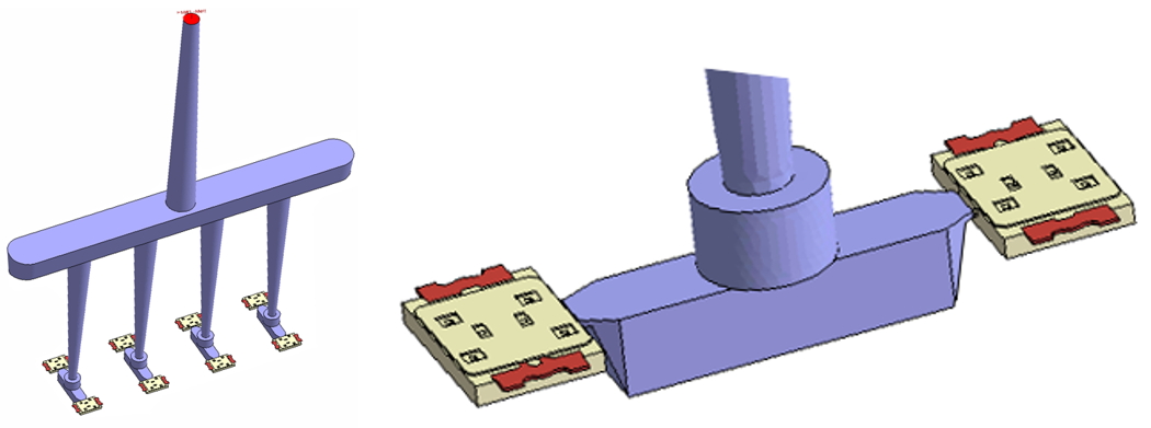
Fig. 1 The original design of the product
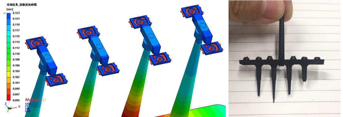
Fig. 2 The unbalanced filling at the sub-runner section
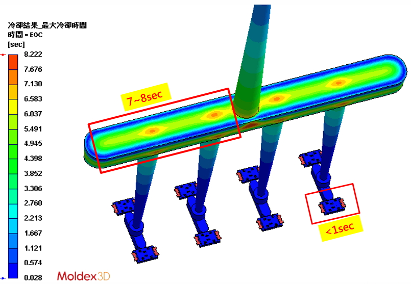
Fig. 3 High cooling time at end of cooling
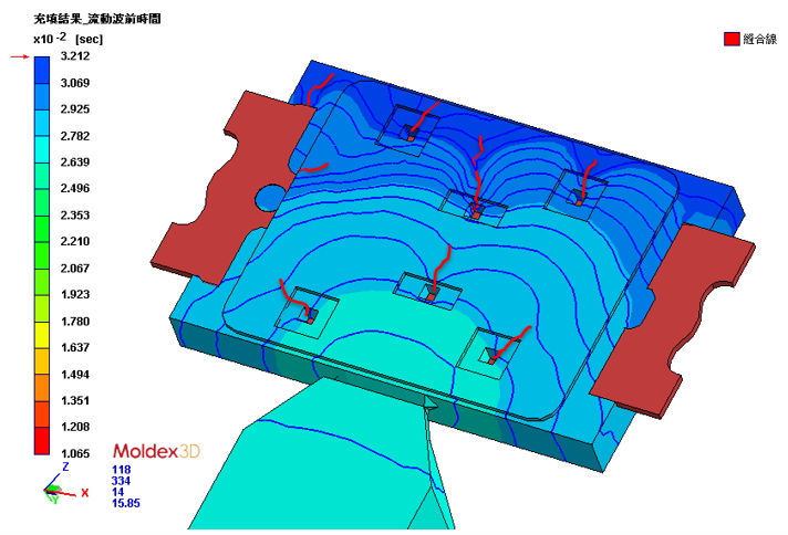
Fig. 4 Potential weld line location
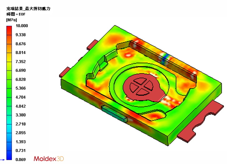
Fig. 5 High shear stress of the product
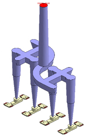
Fig. 6 New design with S-shape runner
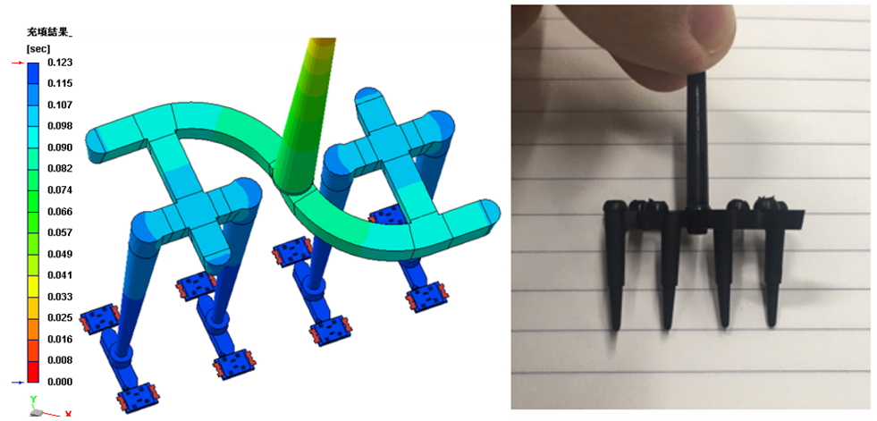
Fig. 7 The flow imbalance has been obviously improved.
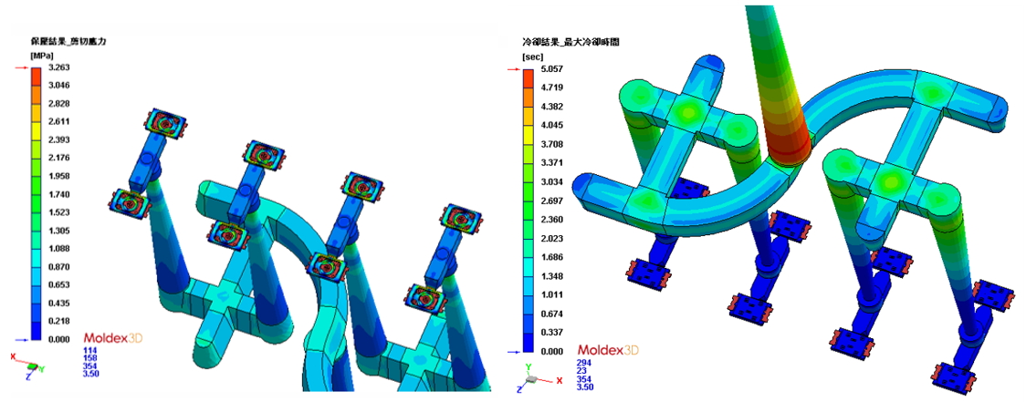
The shear stress is reduced from 7MPa to 3MPa in the new S-shape runner layout (Fig. 8 a) while the max cooling time is reduced from 8sec to 5sec (Fig. 8b).
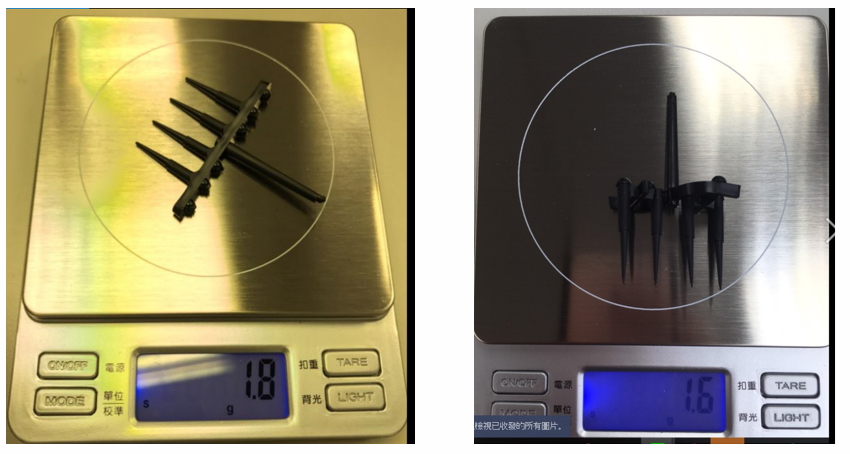
Fig.9 Weight comparison of original design (left) and optimized design (right)
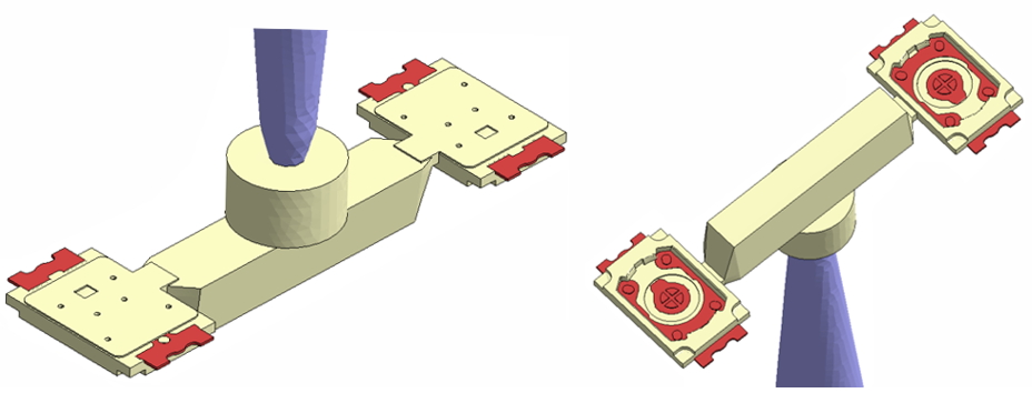
Fig. 10 Final optimal design (a) without concave hole (b) with four external ejector pins
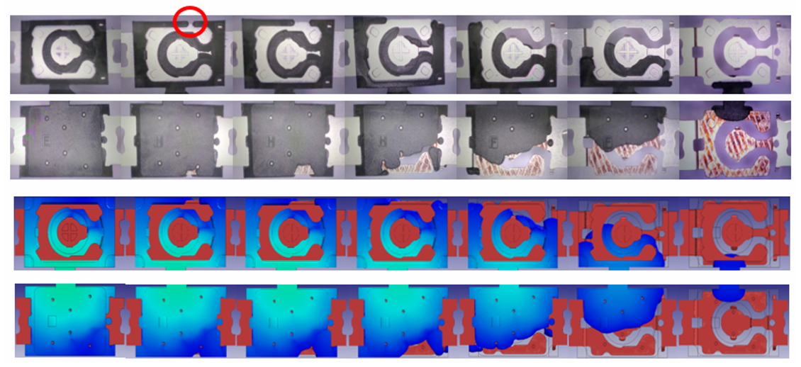
Fig. 11 The trend of the melt front for both simulation and experimental observation was in good agreement.
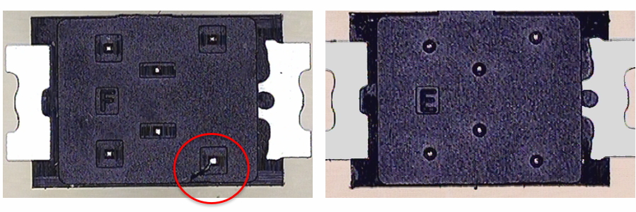
Fig. 12 Weld line comparison of original design (left) and optimized design (right)
Results
Customer Profile